Abstract
As we look at the industry of Air Conditioning, especially in the building sector from design stage to operation & maintenance huge amount of man power is required at different stages like System Design, load estimation, coordination, costing, scheduling, energy simulation and operation & maintenance of facilities & services. These different stages have different expertise involved in carrying out these activities. In addition to this lot of problems arises due to lack of coordination.
Using information model (BIM) from the beginning of a project helps engineers and designers make better decisions earlier in the process. Thus, BIM provides a complete solution from designing to operation & maintenance. BIM is not just a software but it is a collaboration of different software’s, its consist of 2D, 3D, 4D, 5D, 6D and 7D in a single module with which all the activities with respect to the project completion can be made easy. BIM provides a complete solution which can design the system, easily estimate the heat load, costing and estimation, time estimation, visualization and clash detection. These simulation results could help the project to know the energy consumption details by which one can alter the project to achieve energy conservation and maintenance and operation of Air condition system as well.
Introduction
Architects, Civil Engineers, MEP Services Engineers, project management and contractors are the professional people who have to work on board together to complete a project. All these professionals have to coordinate with each other at various stages of the projects form conceptual to the operation and maintenance stage to streamline the progress of the construction with respect to its status, time, cost and quality. This will practically have lot of complications in terms of expectations with the design, cost and many such parameters. No matter how simple a construction project is but from the pre-planning on through to completion there is always a lag in the organizing and comprehending the design data. To encounter these issues BIM is used and analyzed to see if these problems are handled and dealt with.
BIM is a multi-dimensional process which can give us information along with the visuals of 3D,4D,5D,6D and 7D in a common data environment on the model. Project managers of different disciplines will be using specialized software tools to create the required design and information for building, all these files containing the detailed information including all its unique characteristics are stored within the same project for making things easy to work. To analyze the design and showcase the information on these multi-dimensional aspects, a model has been generated with the ideal conditions for showing all the necessary dimensions that are possible by the tool from its conceptual stage to O & M stage.
A duplex villa with 4 BHK having a built-up area of 2800 sft. is modeled with VRF type air-conditioning system considering the Hyderabad climatic conditions. The design which was made in CAD is been imported in Revit and the different dimensions are identified with respect to the HVAC design.
2nd Dimension (Building Data)
BIM being a single point of reference for information and operational activities having multiple dimensions in which the second dimension of the tool in this project gives us the provision for making Heat load estimations, duct sizing, pipe sizing, duct & pipe design. Heat load calculations can be carried out readily if the building envelope properties are given such as walls, floor, ceiling, slab, type of building typology, location of the building, activity in the building, lighting load, equipment load, no. of people, etc., has to be specified. It automatically takes dry bulb temperature, wet bulb temperature, humidity, etc., by specifying the location of the building and these are basically ASHRAE standards.
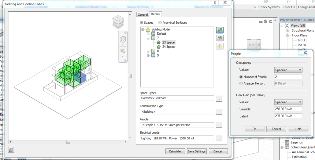
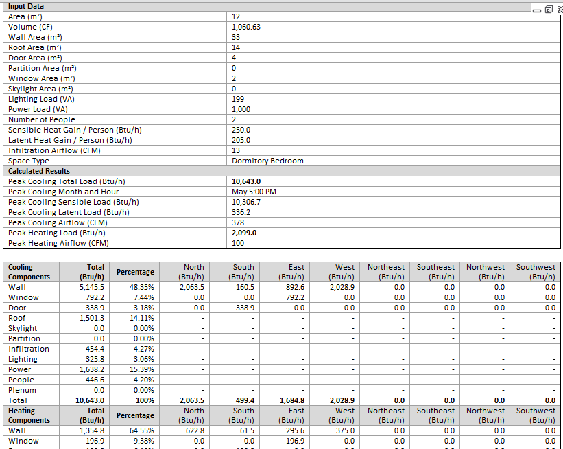
Fig 1a shows the BIM model of the designed building to calculate Heating and cooling loads. Fig 1b shows the results calculated for the BIM Model with the given specifications of the building design.
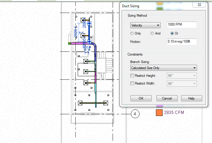
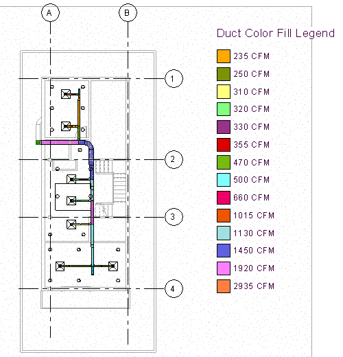
Known with the required heating and cooling loads the desired ducting is designed. normally the duct design is a quit a hectic job to do with the sizing of the duct at different areas to deliver desired conditioning but BIM gives us the duct sizing according to the calculated CFM and FPM just by entering the value of FPM as shown in fig 2a. It automatically calculates frictional losses in the duct and varying FPM in the branch duct and gives the size of branch duct.
3rd Dimension (Shared information model)
There are a number of benefits through the use of modelling over drafting, which include:
- Assisting with coordination.
- Providing briefing output; and
- Client engagement
In 3D model it gives complete visuals of the entire building. Here all the engineering components of the buildings along with its structural and architectural ones can be view in 360 degrees in different spectrum of the view frames such as wire frame, fine, rendered etc.. The modeled building can be visualized by a walkthrough which will give us a tour of the entire building in and out. The significance of the tool lies in its most importance feature of detecting the clashes in the building with respect to the services and the building components and also between the services. The model is imported to the Navisworks which is another plug-in for Revit which will perform the clash detection giving us a visual detection of the clashes and also it can generate report. This clash detection can be done for whole building at once and it can also be done for desired areas of the building.
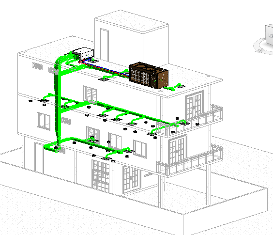
Fig 3a shows the complete HVAC design for the building which simplifies the visual understanding of the Ducting network and its essential components.
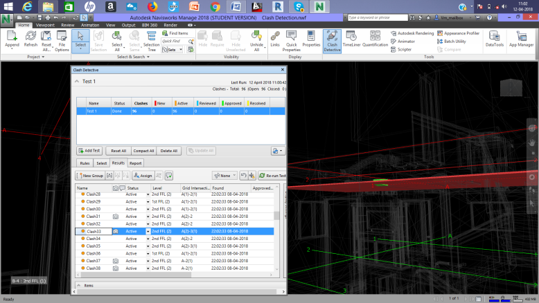
The design of the project has flaws with respect to the coordination which is intentional to show the clash detection test which is shown in fig 3b.
4th Dimension (Construction Sequence)
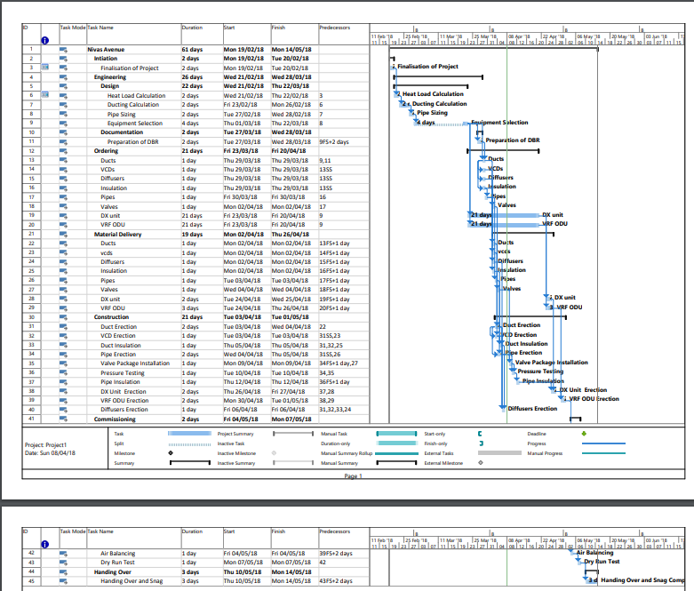
Time estimation and scheduling is an another dimension which can be given by the tool with the help of Microsoft project. This tool by Microsoft project gave us the time estimation for the installation of AC service as 61days for the project from designing to testing and commissioning when the tool is fed with the activities of the work to be done. It will calculate the non working days by itself based on the calendar days. This report can be pluged-in in Navis work and the scheduling of the work to be carried can be prepared. Fig 4a shows us the time consumption by the various activities to be done and on the right hand side of the picture the planning of scheduling as per the time consumption is shown.
5th Dimension (Cost Estimation)
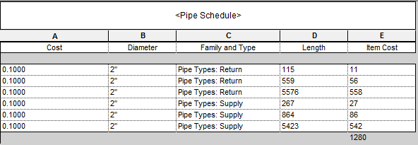
The modeled project had a pretty much information with it to carry on with the execution but the most essential but one is the budgeting. To estimate the budget for the project the cost estimations has to be given to the chosen material and products. This will generate the cost estimation for the desired systems in the building as followed given for the piping and ducting.

6th Dimension (Building Performance)
The sixth dimension intends to present the data on thermal performance of the building. In any conventional air-conditioned building, the air-conditioning system generally consumes the maximum power therefore by taking a little care to minimize energy consumption, will result in substantial savings in the long run.
The main objective of this building energy simulation is to predict the monthly and annual energy consumption of Heating, Ventilation and Air-Conditioning (HVAC) system with respective to the thermal comfort and indoor air quality.
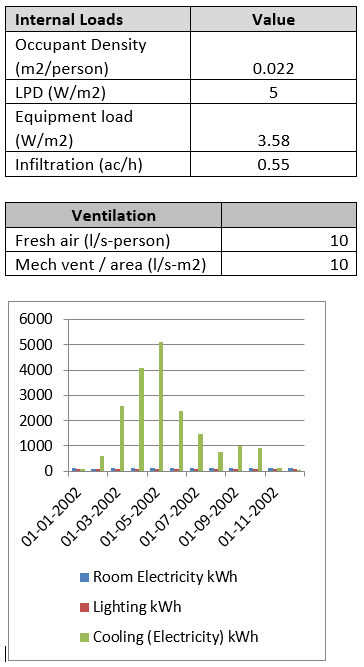
The choice and design of HVAC system is defined here with required calculations and performed simulations for selected HVAC systems, with12 hours as operational time in everyday for 365 days, this simulations were performed for 2 cases i.e. Base case and according to ECBC standards.
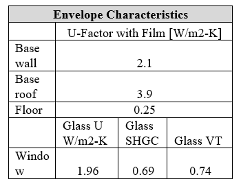
The simulation is performed in Design Builder for the model considering it as a base case. Following are the inputs given to the tool with respect to the building characteristics.

7th Dimension ( Operation & Maintenance)
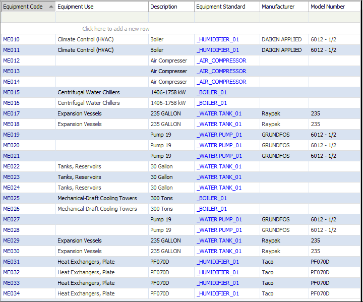
Another significant dimension of BIM in this paper mainly addresses how Building Information modeling can play a significant role in maintenance of HVAC system of the building using ARCHIBUS & Autodesk technology.
In ARCHIBUS-Revit integration one can easily maintain and retrieve information about HVAC System along with all electrical components, including electrical panels, circuits, lighting, receptacles, control systems and more. ARCHIBUS easily create the detailed electronic inventory of the HVAC systems of the facility using pre-defined component standards with key information such as Model number, power requirements, heat load and vendor information. Check for circuit and panel loads and component counts, reporting calculations by building, floor and room from the built-in reporting system. Overloaded circuits and other potential problems can be prevented during the operation level.
The first step in data transmission is to establish a communication link between the two applications, Revit and ARCHIBUS. The link connects the Revit model to a pre-existing project (building and floors) in the database. As a prerequisite, this background information, which includes the building asset, its location, and its organizational attributes, should already exist before a link is attempted. After the link is made, this data is cataloged and synchronized between Revit and ARCHIBUS.
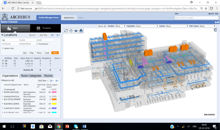
Mapping HVAC Equipment Parameters
Revit models are often populated with a wide range of equipment from a variety of categories like mechanical, electrical and many more. Every individual equipment asset arrives with a significant amount of parametric data already built in its system. Smart Client extension for Revit is designed to map and capture this data through a synchronization process where Revit parameters are mapped to ARCHIBUS tables and fields. This process is done by a BIM specialist ahead of time and in a planned manner in order to capture only FM appropriate data and to ensure the system proper use.
In order to synchronize the asset with the ARCHIBUS database, catalog the HVAC equipment from Revit to ARCHIBUS database. The Extension for Revit also support Web Central functionalities by creating a series of graphics files (Flash and SVG) that are used throughout the applications including mobile. To produce the graphics file user must publish the floor plans by level. Once published users can view and interact with floor plans and equipment without opening Revit. However, ARCHIBUS is not a drafting application, so cannot make architectural changes to the plan. If changes are required, they must be done in Revit and republished for the changes to be reflected in ARCHIBUS.
Conclusion
Communication is made so easy by the mobile phone which has changed the phase of technology, similarly Transformation is what we can see in the project production while using the BIM. Building Information Modeling (BIM) is a per-project collaborative process that provides a framework for stakeholders’ interaction with the purpose of streamlining administration, improving design, setting data-transfer guidelines and responsibilities and, overall, increasing quality while reducing the cost of a project’s production. Following are the benefits that can be seen out of BIM:
- Improved visualization of the project, communication of design intent.
- Improved multidisciplinary collaboration and Reduction in reworks.
- Integrating BIM 4D simulation model brings benefits to participants in terms of planning optimization. Builders and manufacturers can optimize their construction activities and team coordination.
- Integrating BIM with 5D Simulation models enables development of efficient, cost-effective and sustainable construction.
- Integrating BIM with 6D simulation model gives the project team an overall reduction in energy consumption and enhance the building performance.
- Integrating BIM with 7D simulation model optimizes the asset management from the design to demolition phase.
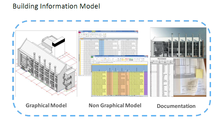
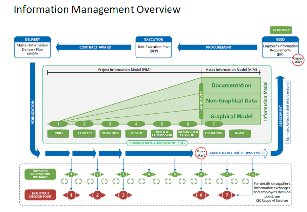
Graphical Model – Developed in specific BIM authoring software using object-based technology to simulate the real world
Non-Graphical Model – Stored either in spreadsheets, databases, web services or other file formats where information associated with graphical information can be stored.
Documentation – Should be bidirectionally linked to both the graphical and non-graphical models to ensure that any information change in either of these is automatically reflected in the latest versions of the documentation.
Together these create the building information model which should be the single source of the truth.
Conserve Solutions will be happy to assist your projects. Our offices are located in India, UAE, Qatar, Saudi Arabia, United Kingdom and Singapore.
Author

